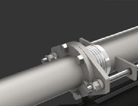
Pipework systems have various changes in direction within itself. As this occurs, pipework systems should have some natural flexibility within it. The following pages will help the engineer use the changes in direction to naturally flex the expansion that will occur.
Expansion within hot pipework is always present. Expansion rates of 74.4 mm over a length of 30 mtrs steel pipework carrying steam at 205ºC needs channeling somewhere.
Items which need to be addressed by the engineer:
- Method of pipework bracketing to allow natural flexibility to occur.
- Pipework material.
- Pipework nominal size.
- Location and layout of pipework, including length.
- Minimum and maximum temperature of pipework, media and ambient. Applicable to ambient temperatures of 0ºC and under.
- Working and test pressure of pipework media.
- Connection points to plant etc.
- Structure of building.
Once we have addressed all these items, then we can look at solutions.
To help take into account the above items, the engineer should use pipework anchors. Pipework anchors can separate large, complicated pipework systems into smaller more manageable systems.
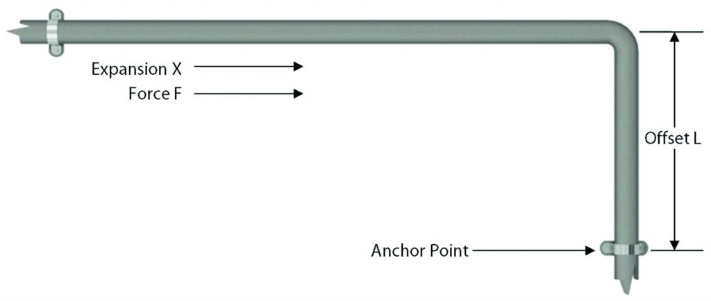
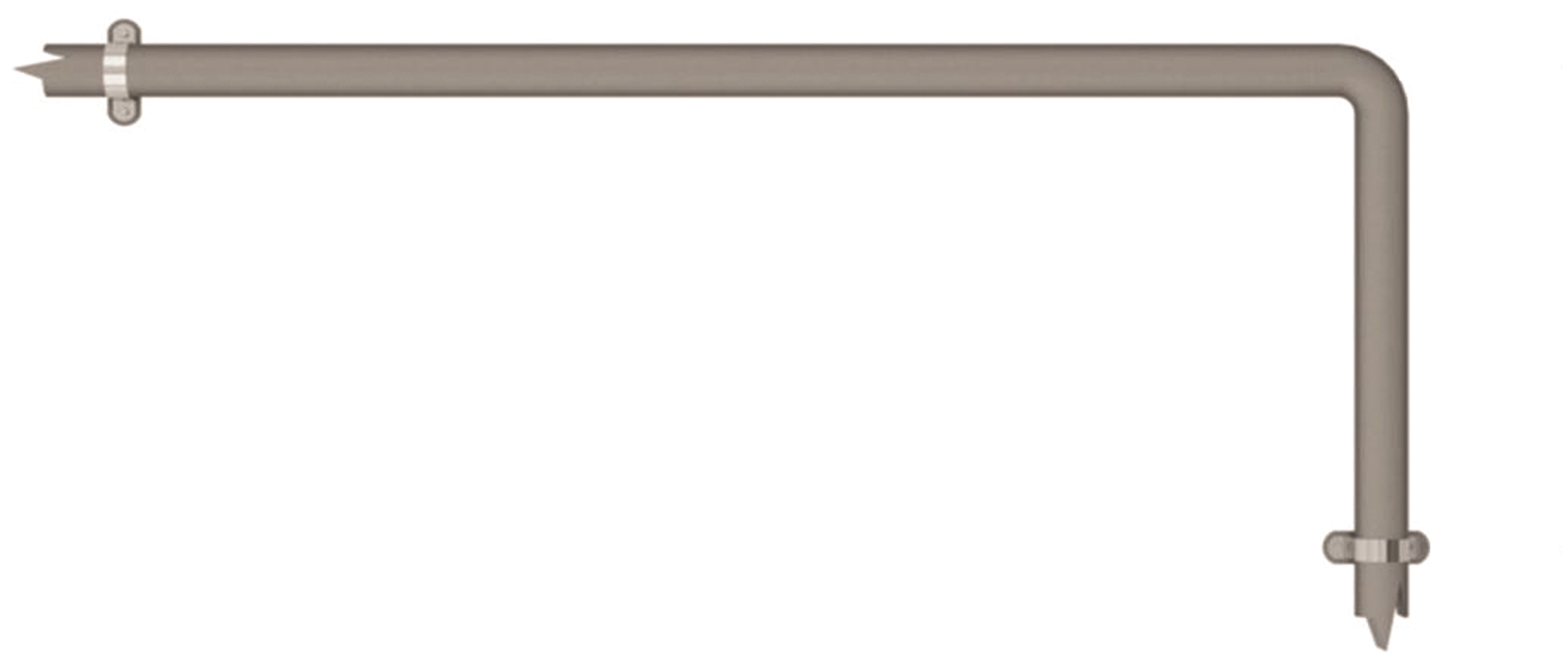
Positioning the anchors so an offset occurs between the anchors could naturally compensate the expansion.

The force imposed upon an anchor is primarily made up from two areas:
- Force to deflect pipework offset
- Frictional force due to pipework bracketry
Forces subjected onto the anchor positions can be calculated using the following formulae:-
F = 24IX/L3 for carbon steel pipes.
F = 8.4IX/L3 for carbon steel pipes.
F = Force in Newtons
I = Moment of Inertia in cm4. Applicable to pipework size (See Page 113)
X = Expansion in mm
L = Length of offset in metres (shortest length)
You will also need to add to this result the forces encountered via frictional resistance of pipework bracketry on the pipework.
Examples of frictional resistance can be calculated using the following formulae:-
F = L x 15 x (I/D)/25
F = Force in Newtons
L = Length of pipework (longest length)
15 = 15 Newtons which is the frictional resistance based on the use of a EXCO-253 Slide Guide
I/D = Inside diameter of the pipework


